What Is Photo Rendering and How Designers Use It
What is photo rendering? See how a scene becomes an image, how design teams use renders, and what a convincing picture cannot prove.
Photo rendering is the computer process that turns a scene description or a design view into a two-dimensional image, and that image is a calculated or predicted picture, not a photograph of a built place. The familiar advice to make it look as realistic as possible misses the more important question: what can the viewer trust it to show?
A polished kitchen can make an undecided finish look specified. A luminous facade can make an untested lighting scheme look resolved. For architects and students, rendering is most useful when the image's purpose is clear before anyone starts judging its beauty.
What Photo Rendering Actually Produces
Photo rendering produces a synthesized image from design inputs. In a calculated workflow, those inputs include geometry, camera position, materials, lighting and textures. The output is a picture of the proposal from a chosen viewpoint, not the proposal's complete technical description.
The word photo can cause confusion. It usually describes the image's photographic appearance, not how it was captured. A realistic render might resemble a camera exposure even though nobody could stand in that room yet.
What kind of image you are looking at
| Image type | How it is made | What it can show | What it cannot prove |
|---|---|---|---|
| Photograph of a built place | A camera records existing light and surfaces | Appearance at that moment | A design that does not exist yet |
| Hand illustration or collage | A person draws or assembles the picture | Mood and design intent | Measured light or exact materials |
| Physically based render | Software calculates light from geometry, camera, materials and lights | Proposed form and light when inputs are accurate | Approval, buildability or that the place exists |
| Generative or image-based render | A model predicts a picture from a sketch, view, photo or text | Fast look and atmosphere alternatives | Exact geometry, intended ambiance or code compliance |
Start with the photograph. It records something that existed in front of a camera, although framing, exposure and editing still affect what viewers see. An illustration or collage takes a different route: the author selects, draws and assembles elements to communicate an idea.
The rendering rows describe distinct practices. Physically based synthesis models how light interacts with a scene. Generative rendering predicts a plausible picture from visual or written inputs. Both can look photographic, so appearance alone doesn't tell you which process produced the file.
The kitchen-window test
Say you're reviewing a kitchen renovation. Someone photographs the existing room at noon, an illustrator paints an imagined evening version, and a visualization specialist renders the proposed glazing within a digital scene.
The photograph documents the existing condition. The painting communicates an interpretation. The calculated render lets the team examine the proposed glazing under selected assumptions, provided those assumptions describe the proposed product and environment. Neither photographic realism nor a convincing reflection establishes that the specification has been approved.
Review rule: Name the image-making method before asking people to make a decision from the image.
This distinction matters when students pin work beside technical drawings or architects place alternatives in a client deck. Viewers can mistake presentation polish for design resolution. Before the review, label each image photograph, illustration, calculated render or predicted render, then state which decision it supports.
How a Scene Becomes a Calculated Image
Consider a north-facing living room with a broad window, pale walls and a stone hearth. The digital model establishes the room's boundaries, but it doesn't yet establish what the room looks like. The renderer still needs a camera, illumination and descriptions of how the surfaces respond to light.
Begin with matte plaster around the hearth. Replace it with glossy stone while keeping the geometry and base color similar. The stone can reflect recognizable parts of the window, while the plaster distributes reflected light more broadly.
Lower the sun in the lighting setup and compare again. Depending on the site, season and surrounding obstructions, that change may alter the sky illumination or admit direct light from another opening. A north-facing label alone doesn't justify painting a dramatic sunbeam across the floor.
The scene is a set of instructions
The diagram separates the inputs that must work together before the software can calculate an image.
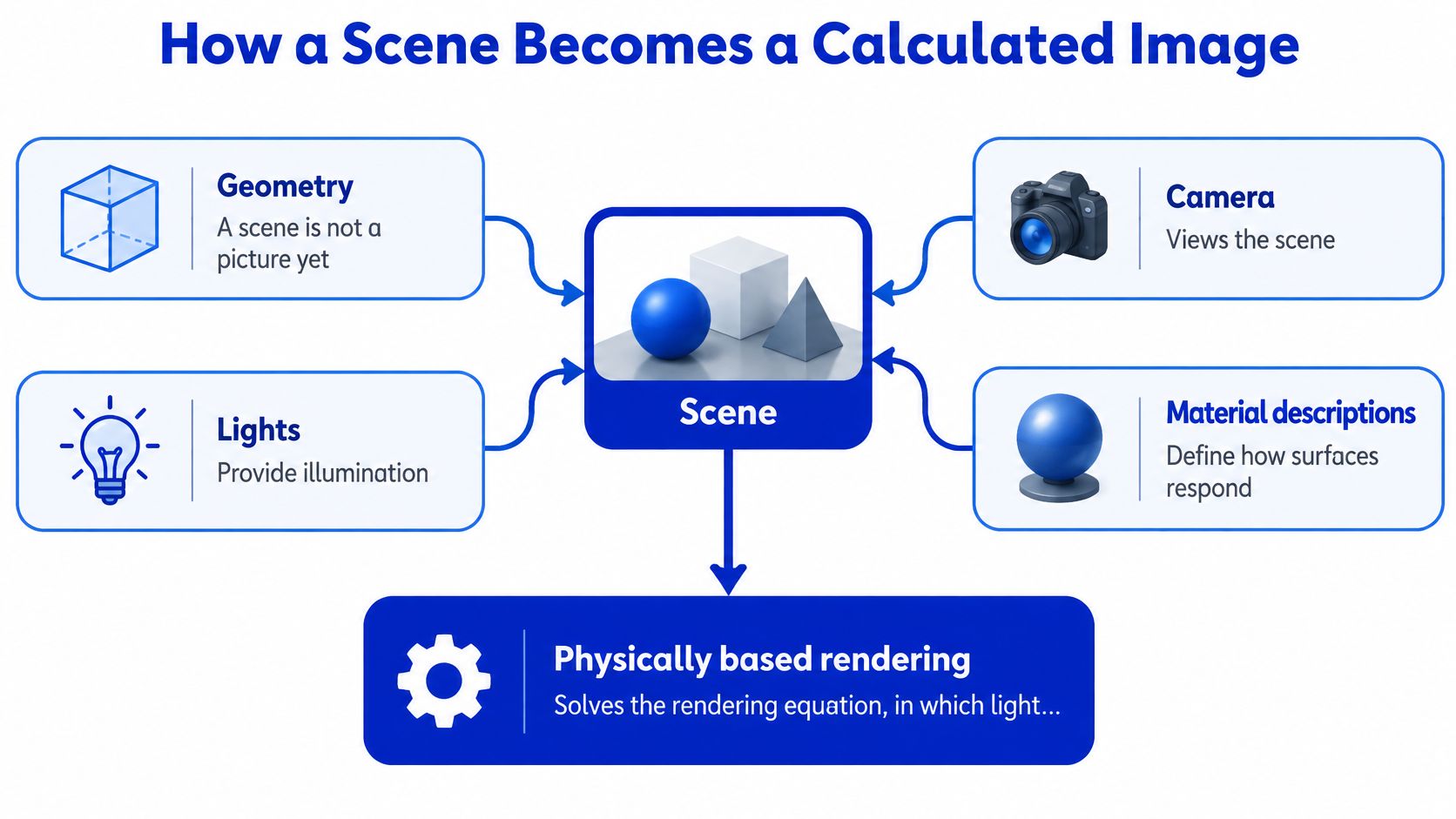
Each input answers a different practical question:
- Geometry: Where are the walls, window reveals, furniture and other surfaces?
- Camera: From where are we looking, and what falls inside the frame?
- Lights: What illuminates the room, including the sky and artificial fixtures?
- Materials and textures: How do surfaces reflect, transmit or emit light, and where do their visible patterns occur?
A texture image of stone isn't a complete stone material. It might describe the pattern, but the renderer also needs information about reflectance and roughness. Otherwise, the pattern can look like a photograph pasted onto an unrelated surface.
Camera choices matter too. Moving the viewpoint changes which reflections are visible and how surfaces overlap. For a useful material comparison, keep the camera fixed rather than making each alternative attractive from a different angle.
The rendering equation in plain language
In physically based rendering, the rendering equation describes light leaving a surface as emitted light plus incoming light reflected toward the viewer, weighted by the material's response and the angle of incidence, as explained in National Taiwan University's shading lecture notes.
The material-response term is the bidirectional reflectance distribution function, or BRDF. In plain language, it describes how a surface redirects light arriving from one direction toward another direction. That's why a material can't be defined by color alone.
Return to the hearth. The plaster and stone may share a similar pale tone, yet their highlights and reflections differ. Change the viewing direction, and the stone's reflected window may move even though the stone itself hasn't changed.
Ray tracing constructs paths between image pixels, scene surfaces and lights. Path tracing samples possible light paths, often using Monte Carlo methods, to estimate their combined contribution. Increasing samples generally reduces noise but requires more computation.
A clean image means the calculation has settled sufficiently for presentation. It doesn't mean the inputs were correct.
For production planning, use the guide to calculating render time to think through the workload before committing to final output. Test difficult glass, dark corners and reflective finishes in a preview rather than discovering problems after the full image finishes.
Why modern renders can show more than shape
The underlying methods developed incrementally. The Stanford-hosted history of computer graphics traces hidden-line and hidden-surface developments from 1963 to 1970, followed by Gouraud shading in 1971, Phong shading in 1974, anti-aliasing research in 1977, Whitted's ray tracing in 1980, radiosity research in 1984–1985, and Kajiya's rendering equation in 1986.
Those developments addressed different visual problems:
- Visibility methods established which edges and surfaces a viewer should see.
- Shading methods improved the appearance of diffuse surfaces and specular highlights.
- Anti-aliasing addressed jagged boundaries in sampled images.
- Ray tracing incorporated effects such as reflections, refractions and shadows.
- Radiosity and light-transport methods accounted for illumination exchanged between surfaces.
In the living room, these capabilities distinguish a flat pale wall from a softly illuminated one. They also explain color bleeding, such as reflected color from a red wall affecting a nearby white ceiling. No single realism setting replaces the scene information needed to produce those effects.
For broader visual context beyond architectural practice, you can explore the history of CGI with AI Image Detector. The useful lesson for a working designer is simpler than the mathematics: describe material, lighting and camera intent separately, and preserve the geometry that gives those instructions meaning.
Two Ways Design Teams Produce Renders
Choose the production method by the question you're asking. If you need consistent comparisons of modeled form and lighting, start with a model-based scene. If you're exploring a range of finishes or visual directions, an image-based workflow can start with less scene preparation.
A conventional ray tracer evaluates geometric intersections and light effects, with computational work tied to rays, scene complexity and shading operations; interactive ray-tracing research published by ACM describes this model-based approach. In practice, material evaluation and additional light bounces also affect the workload. A small-looking change to reflective glazing can therefore require another substantial calculation.
How a design view becomes a render
| Starting point | What stays fixed | Best used for | Main risk |
|---|---|---|---|
| Full 3D scene with materials and lights | Modelled geometry, camera and light setup | Consistent light and material studies | Long setup and re-render time |
| Hand or CAD line sketch | Line structure only, if the tool respects it | Early look before a model exists | Invented depth, openings or scale |
| Photograph of an empty or existing room | Walls, windows and camera if staging is constrained | Furnishing and material alternatives | Furniture or light that was never specified |
| Model view exported as an image | Camera and geometry in the source view | Presentation from SketchUp, Revit, Rhino, Blender or 3ds Max | Details inferred beyond the view |
| Text brief alone | Only the written description | Concept images with no model yet | No shared geometry to check later |
Model-based rendering gives the team a scene they can inspect and revise. You can locate the window, change its modeled dimensions and calculate another view. Its consistency is valuable, but only when the scene is maintained alongside the design.
Image-based rendering starts from visible information rather than a complete light-transport scene. The system may interpret a sketch's lines as a recess, opening or material boundary. That flexibility helps early exploration, but it also creates opportunities for unintended invention.
A hybrid workflow needs constraints
Keep the source view visible while reviewing each generated alternative. Check the silhouette, opening locations, floor boundaries and perspective before discussing color or atmosphere. If the requested revision concerns only a countertop, mask that region instead of inviting changes throughout the room.
A furnished photograph needs a different instruction from an empty-room staging image. Specify whether existing furniture should remain, be replaced or be removed. Don't assume the system understands which objects are part of the proposal.
For site work, the guide to landscape design software for 3D workflows provides context for choosing an appropriate starting environment. The governing choice remains exact form and light versus exploratory appearance, not which method produces the prettiest first image.
Where Rendered Images Sit in Design Work
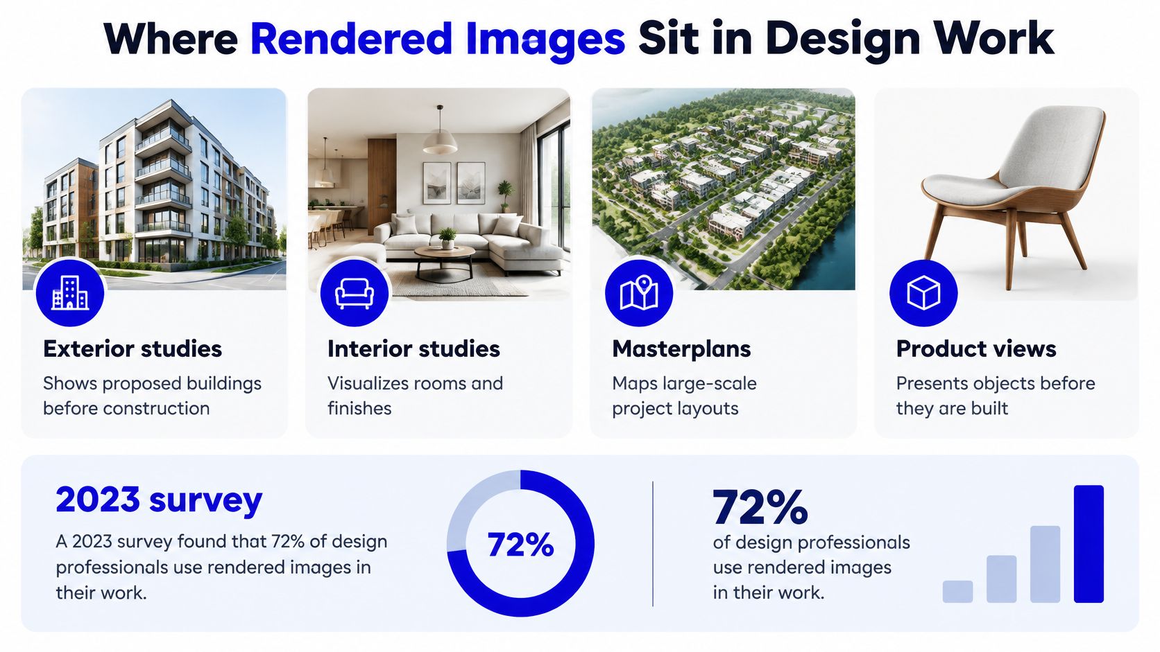
A render belongs wherever a team needs to discuss a proposal's visible consequences. Exterior studies support conversations about massing and facade character. Interior studies help clients compare finishes, while site and masterplan views communicate relationships that can be difficult to read from linework alone.
For many practitioners, these aren't occasional presentation tasks. In a 2023 survey reported in 2024, more than 75% of over 2,000 AEC professionals said they used real-time rendering daily or at least twice per week, according to Architect Magazine.
Match the view to the meeting
A productive review starts with a question, not an export button. Ask whether the client is choosing a facade treatment, comparing planting character or evaluating furniture placement. Then choose a view that exposes the relevant differences without introducing distracting changes.
The audience also affects the image. A contractor discussing junctions needs different supporting information from a developer reviewing the proposal's public-facing appearance. Pinnacle Property Media's examples of architectural visuals for developers and contractors offer a useful reference for those presentation contexts.
Follow a file through a project week
On Monday, export a sketch or model view for an options meeting. Give the source a clear revision name and record the camera so the team can return to it. Put the question beside the image, such as whether a lighter facade treatment makes the entrance easier to identify.
At midweek, compare material alternatives from that same view. Keep the surroundings and framing consistent so reviewers don't choose an option because it has better trees or more flattering exposure. For an interior furnishing review, the living-room staging guide can help frame the task around the existing room rather than an unrelated reference image.
Handoff discipline: Keep each alternative beside its source and record the decision beside the alternative.
By Friday, prepare the selected still for the presentation medium and inspect the exported file, not just the working preview. Check text legibility, cropping and whether an enlarged image reveals artifacts that weren't obvious on screen. Include a short camera move only when motion helps explain the spatial relationship under discussion.
Conventional scenes need coordinated material and lighting setup; image-based passes can begin from an available view. Either way, scattered attachments and ambiguous revisions make review harder. Use the render to settle appearance questions, and bring the drawing, model or calculation when the meeting must settle dimensions or performance.
What a Convincing Render Can and Cannot Prove
A study of generative images reported 76% for spatial depiction but only 25% for ambiance accuracy, according to the study published in Springer's Architecture, Structures and Construction. Within that study, depicting the intended space and conveying its intended experience were distinctly different achievements.
That contrast challenges a common assumption: a believable room isn't necessarily the right room in the ways that matter. Photorealism can raise misunderstanding risk when viewers accept persuasive details without asking how those details were established.
Look past the dusk glow
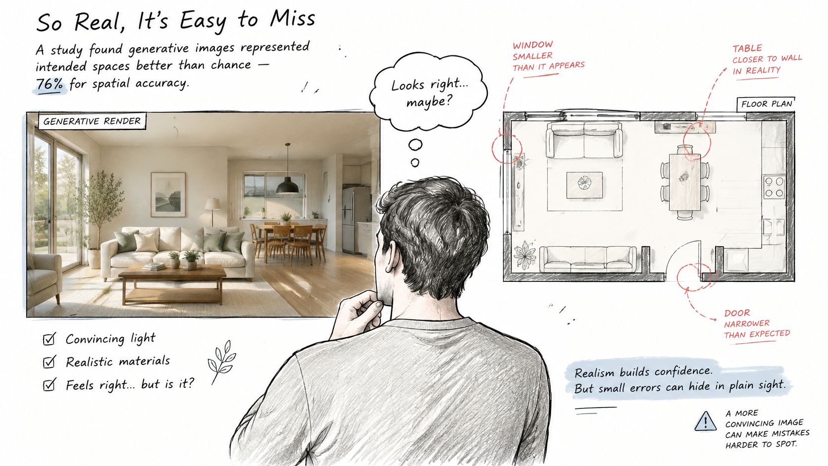
Say a client sees a dusk facade with warm interiors, mature trees and understated glass reflections. The image suggests comfort and completion. Yet the glass reflectance, planting positions and interior brightness may be presentation choices rather than verified project conditions.
The same problem applies to a calculated render if the scene contains generic materials or simplified surroundings. A physically based method calculates the supplied assumptions; it doesn't validate the specification, survey or engineering behind them.
Check the claims before approving the image
Use this review checklist before the image supports a design or approval decision:
- Geometry and scale: Compare opening positions, ceiling heights, furniture proportions and circulation space against the current model or drawings. Investigate discrepancies rather than explaining them away as perspective.
- Materials: Match visible finishes to the specification or label them as exploratory. Check texture scale, joint direction and whether a reflective surface has become misleadingly transparent.
- Lighting and season: Confirm the stated time of day, orientation, season and artificial-light assumptions. Don't treat an attractive exposure as a daylight-performance result.
- Context: Verify neighboring buildings, terrain, access and planting. A missing obstruction can change both the composition and the apparent quality of the proposal.
- Intended use: State whether the image supports concept discussion, material selection or another defined review. Identify unresolved elements explicitly.
A render alone doesn't establish plan organization, structural feasibility, environmental performance, regulatory compliance or downstream editability. Those questions require the relevant design records and specialist checks. A convincing image file also doesn't guarantee that the depicted arrangement exists as an editable model.
A persuasive image is a communication, not a certificate.
Drawings, models, specifications and calculations carry the technical claims; the render illustrates selected consequences of those claims. Keep that distinction visible in the meeting minutes as well as the presentation. Withhold approval language until the checklist is complete, and record any remaining assumptions alongside the image.
Label the Render Before You Present It
Attach a short provenance record to the presentation file so another person can understand how it was made:
- Source: Retain the original photograph, sketch or exported model view.
- Instructions: Save the prompt and identify whether each reference guided geometry, material, style or atmosphere.
- Software: Record the application and model version where available, together with accessible generation settings.
- Changes: Note major edits, compositing, enhancement and post-processing.
- Label: Use plain descriptions such as conceptual, composited or AI-assisted, with the intended use.
Don't rely on automatic disclosure. An analysis of 50 widely used AI image systems found that 38% included some form of machine-readable marking, while 8% used deepfake labeling. Viewers shouldn't have to infer an image's origin from its visual style.
Make the next pass traceable
For a first pass, use a view the team already has. State what it shows, what should remain unchanged and how the proposed result should read. Save the output as a new file rather than overwriting the source.
In mnml.ai, Studio starts from a sketch, photograph or view from SketchUp, Revit or Rhino, while Sketch to Image can turn a hand-drawn or CAD line sketch into a photoreal image without building a model first. That makes it possible to explore appearance before a conventional rendering scene is ready.
A slightly less polished image with a usable record is more valuable at handoff than a beautiful file nobody can reconstruct. Pick a current view, make a rendering pass and attach the provenance notes before it enters the client deck.
mnml.ai offers image-based architectural visualization from sketches, photographs and model views, with tools for refining selected areas and comparing alternatives. Visit mnml.ai to render a current design view, then present the result beside its source with a clear label of what it's intended to show.